[X131] sine encoder
|
Supported hardware: |
KW-R06 / KW-R16 / KW-R07 / KW-R17 / KW-R25 / KW-R26 / KW-R27 / |
||
|---|---|---|---|
Description
This interface supports the following encoder types:
E, F, I, P, Q, S, T, U, V,
Technical data
- The maximum input frequency is 200 kHz
- Input signals according to RS485 specification
- Encoder line length:
- DT7-28-20-EOO-2600-B5 (part no.: A1216AD)
- SKT7-55-20-EBW-5200-DB-B9 (part no.: A1706ED)
- SKT7-55-20-EOW-5200-DB-B9 (part no.: A1706ED)
- SKWS13-150-6-EOW-800-B5 (part no.: A1024AC)
- SKWS13-150-6-EOW-800-B5*AT (part no.: D611AC)
|
Encoder designation |
ERN 1380 |
ECN 1113 EQN 1125 |
ECN 113*) |
ECI 119 EQI 1130 |
SKS 36 SKM 36 |
SEK 37 SEL 37 |
EKS 36 EFS 50 EKM 36 EFM 50 |
|---|---|---|---|---|---|---|---|
|
AMK Encoder designation |
I |
E / F |
P / Q |
S / T |
U / V |
Y |
|
|
max. Encoder line length [m] |
100 |
100 KW-R25: 25 m |
25 |
100 KW-R25: 25 m |
100 |
100 |
100 at AWG 22 30 at AWG 26 |
| *) |
The encoder ECN113 does not have a extended voltage range and can therefore only be employed with line lengths up to a maximum of 25 m. The encoder is built into the following motors: |
|
|
The above mentioned line lengths are valid only with the specified voltage ranges and the cable cross-sections recommended by AMKmotion. |

Design
|
Type |
Poles |
Class |
|---|---|---|
|
D-SUB |
15 |
Socket |
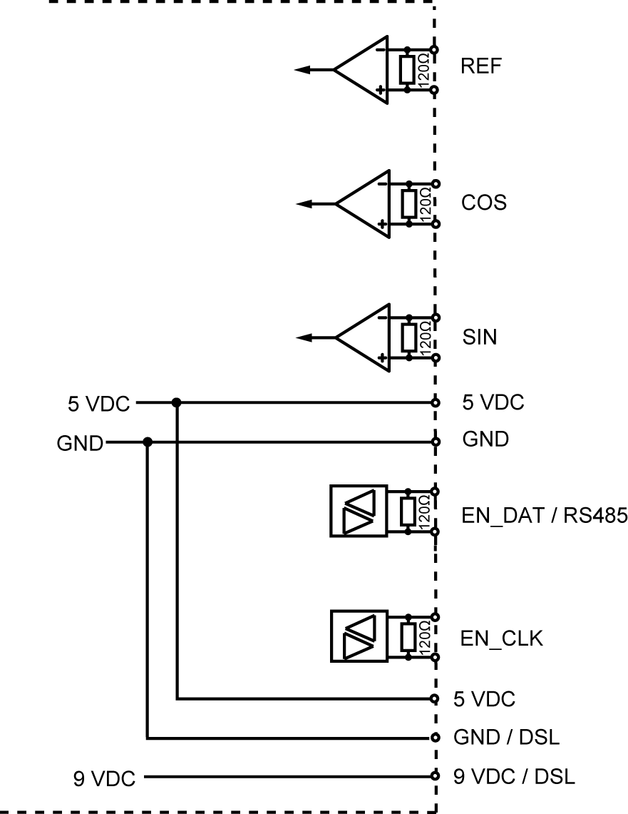
Assignment
|
[X131] |
Connection |
I-encoder |
E- / F-encoder |
P |
S- / T-, |
Y-encoder |
|---|---|---|---|---|---|---|
|
front view, device side |
1 |
-REF |
- |
- |
- |
- |
|
2 |
+REF |
- |
- |
- |
- |
|
|
3 |
-COS |
-COS |
- |
-COS |
- |
|
|
4 |
+COS |
+COS |
- |
+COS |
- |
|
|
5 |
-SIN |
-SIN |
- |
-SIN |
- |
|
|
6 |
+SIN |
+SIN |
- |
+SIN |
- |
|
|
7 |
5 VDC 1) |
5 VDC 1) |
5 VDC 1) |
- |
- |
|
|
8 |
GND |
GND |
GND |
GND |
- |
|
|
9 |
- |
-EN_DAT |
-EN_DAT |
-RS485 |
- |
|
|
10 |
- |
+EN_DAT |
+EN_DAT |
+RS485 |
- |
|
|
11 |
- |
-EN_CLK |
-EN_CLK |
- |
- |
|
|
12 |
- |
+EN_CLK |
+EN_CLK |
- |
- |
|
|
13 |
- |
5 VDC1) |
5 VDC1) |
- |
- |
|
|
14 |
GND |
GND |
GND |
GND |
-DSL 3) |
|
|
15 |
- |
- |
- |
9 VDC 2)3) |
+DSL 3) |
|
1) |
5 VDC ±5 % max. 350 mA |
|
2) |
KW-R06 / KW-R16 / KW-R07 / KW-R17 / 9 VDC ±15 % at load; max. 400 mA, 12 VDC ±20 % in idle |
| 3) |
KW-R26 / KW-R27 / 9 VDC ±15 % at load, max. 400 mA, short-circuit-proofed |
Connection
|
E- / F- / I- /P- / Q- / S- / T- / U- / V-encoder |
Y-encoder |
|
|---|---|---|
| Cable | E- / F- / P- / Q- encoder: |
Hybrid cable DSL: twisted pair, shielded 4 x 1,5 mm2+(2 x 0,75 mm2)+(2 x AWG22 or AWG26) 4 x 0,5 mm2+(2 x 0,75 mm2)+(2 x AWG22 or AWG26) z. B. HELUKABEL and Tecni |
| 4 x 2 x 0.25 mm2twisted pair, + 4 x 0.5 mm2 shielded | ||
| I- / S- / T- / U- / V-encoder: | ||
| 4 x 2 x 0,5 mm2 twisted pair shielded | ||
|
Shield connection |
Shielded on both sides |
Shielded on both sides |
|
Cable assembly |
D-SUB connector 15-pin with metallized casing |
|
|
Note |
The shield of the cable has to be grounded by the screw connection in the plug housing on the motor side. The shield mesh is everted over the terminal insert. After screwing together, the shield is placed over the contact spring and the plug housing on the mass. |
|
Controller input circuit
|
Encoder evaluation |
I-encoder |
E- / F-encoder |
S- / T-, |
P- / Q-encoder |
Y-encoder |
|
|---|---|---|---|---|---|---|
|
Data |
Sine encoder |
EnDat 2.1 |
Hiperface |
EnDat 2.2 light |
Hiperface DSL |
|
|
Voltage supply to the encoder |
||||||
|
Input voltage |
VDC |
5 ±5 % 1) |
5 ±5% 1) |
9 ±15% 2) |
5 ±5% 1) |
9 VDC ±15% 4) |
|
Output signals of the analog tracks |
||||||
|
Output voltage |
VSS |
0.6 - 1.1 |
- |
- |
||
|
Offset |
V |
2.5 ±0.5 |
- |
- |
||
|
Output signal of the homing track |
||||||
|
Resting value |
mV |
200 |
- |
- |
- |
- |
|
Signal width |
° el. |
90 ... 270 |
- |
- |
- |
- |
|
1) |
5 VDC ±5 % max. 350 mA |
|
2) |
9 VDC ±15 % at load; max. 400 mA, 12 VDC ±20 % in idle |
| 3) |
EnDat 2.2 light means, that the encoder supports EnDat 2.2, which is used only with the commands of EnDat 2.1 from the AMK controller. |
| 4) |
9 VDC ±15 % at load, max. 400 mA, short-circuit-proofed |
Encoder signal
Analog tracks
|
2,5 V |

|
Homing signal

To receive a unique signal, the homing signals (+REF and -REF) must overlap by at least 200 mV. The overlap range must be at least 90 °el. and maximum 270 °el. long.
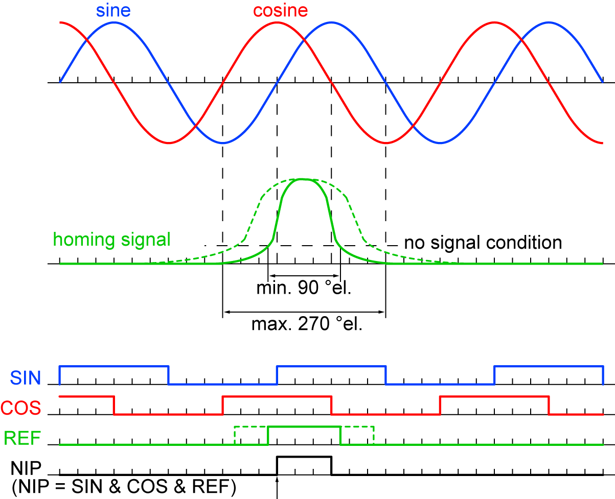
The zero pulse NIP is determined in the controller. A logic AND link of SIN, COS and REF results in the NIP signal. The positive edge (for right-turning motor) is evaluated for exact determination of the zero pulse.
Encoder signal evaluation
In ID32953 'Encoder type' is defined how to evaluate the incoming encoder signals.
