Inductive encoder
Inductive encoders contain a sensor and a signal encoder.
The signal encoder consists either of permanent magnets, which are aligned alternately, or of a magnetoresistor, in whose surface indentations have been made so that the permeability of the air gap changes cyclically.
The sensor records the strength of the magnetic field on the surface of the signal encoder and converts this information into electric signals.
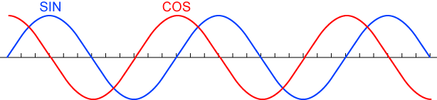
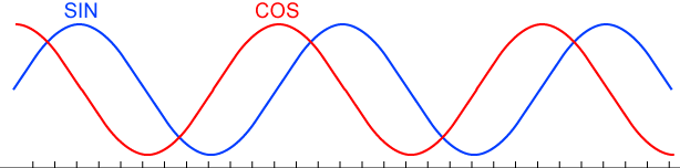
If the signal encoder (magnetoresistor / permanent magnets) moves relative to the sensor, this generates a sine-shaped periodic signal in the sensor.
The number or periods through a rotor rotation is decisive for the accuracy of the actual position value.
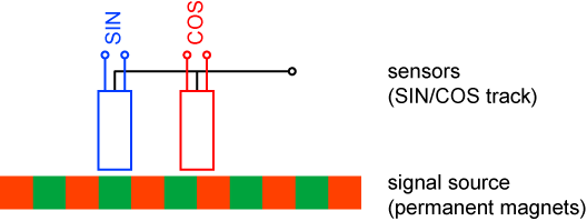
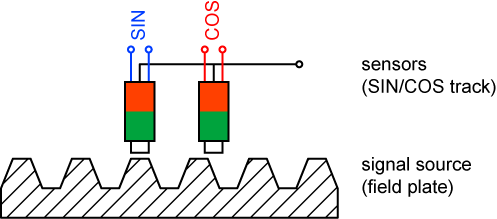
The position of the rotor cannot be uniquely determined with a single sine signal. Two sensors, electrically offset by 90° are used that generate a sine and a cosine signal. Through evaluation of both signals, the rotor position and direction of rotation can be uniquely determined.
Inductive encoders are more robust against dust and oil contamination (except metal dust) but are more prone to magnetic disturbances and stray fields. The resolutions are lower than with optical encoders.
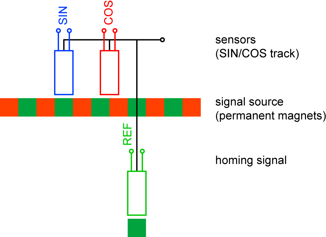
Encoder with permanent magnets
For encoders with alternately arranged permanent magnets, the sensor measures the strength of the magnetic field directly. Since these permanent magnets cannot be infinitely narrow, the achievable resolution is limited.
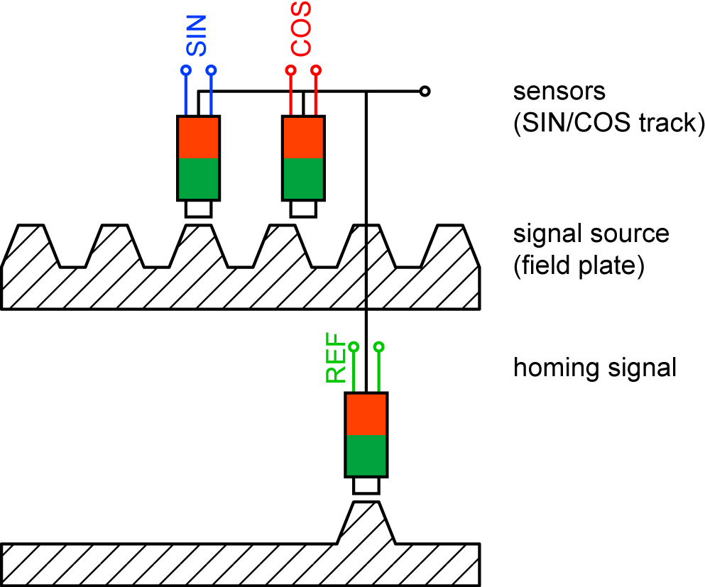
Encoder with magnetoresistor
The width of the air gap between sensor and signal encoder changes through the indentations of the signal encoder. This also changes the magnetic resistance, the permeability. The sensor detects the change in a magnetic field subject to this air gap.
Homing signal
|
|
|
|
|
|
|
|
|
|
|