I-encoder
The following data are typical guidelines and can therefore deviate for the specific motor.
|
Encoder type |
Technical description |
Manufacturer / |
|---|
| I |
|
Heidenhain ERN 1380 ERN 1381 |
|
Resolution: 512 / 1000 / 1024 / 2048 periods/revolution |
||
|
Measuring principle: optical ( ) |
Principle
If an analog encoder has several SIN/COS periods per rotation, an absolute position reference within a motor rotation is possible. The rotor rotating field of the permanent magnets of a synchronous motor is not aligned on the stator rotating field. For synchronous motors with I encoder, alignment takes place automatically in the drive controller through the software commutation function after each power on and initial setting of the controller enable.
Output signals
Signal sequence depicted for clockwise turning of the motor shaft with direction of view toward the A bearing side of the shaft.
| 2,5 V | 
|
| 2,5 V | 
|
The encoders are temperature-compensated and deliver standardized output signals.
| Data |
I-encoder |
|
|---|---|---|
|
ERN 1380 |
||
|
Sine-shaped voltage signals |
||
| Signal level |
VSS |
1 ±0.2 |
| Offset |
V |
2.5 ±0.5 |
| Resolution |
Per./rotation |
512 / 1024 / 2048 |
| Symmetry deviation |
|
≤0.065 |
| Signal ratio |
|
0.8 - 1.25 |
| Phase angle |
° el. |
90 ±10 |
|
Homing signal |
||
| Effective fraction |
V |
≥0.2 |
| Resting value |
V |
≤1.7 |
| Signal-to-noise ratio |
V |
0.04 - 0.68 |
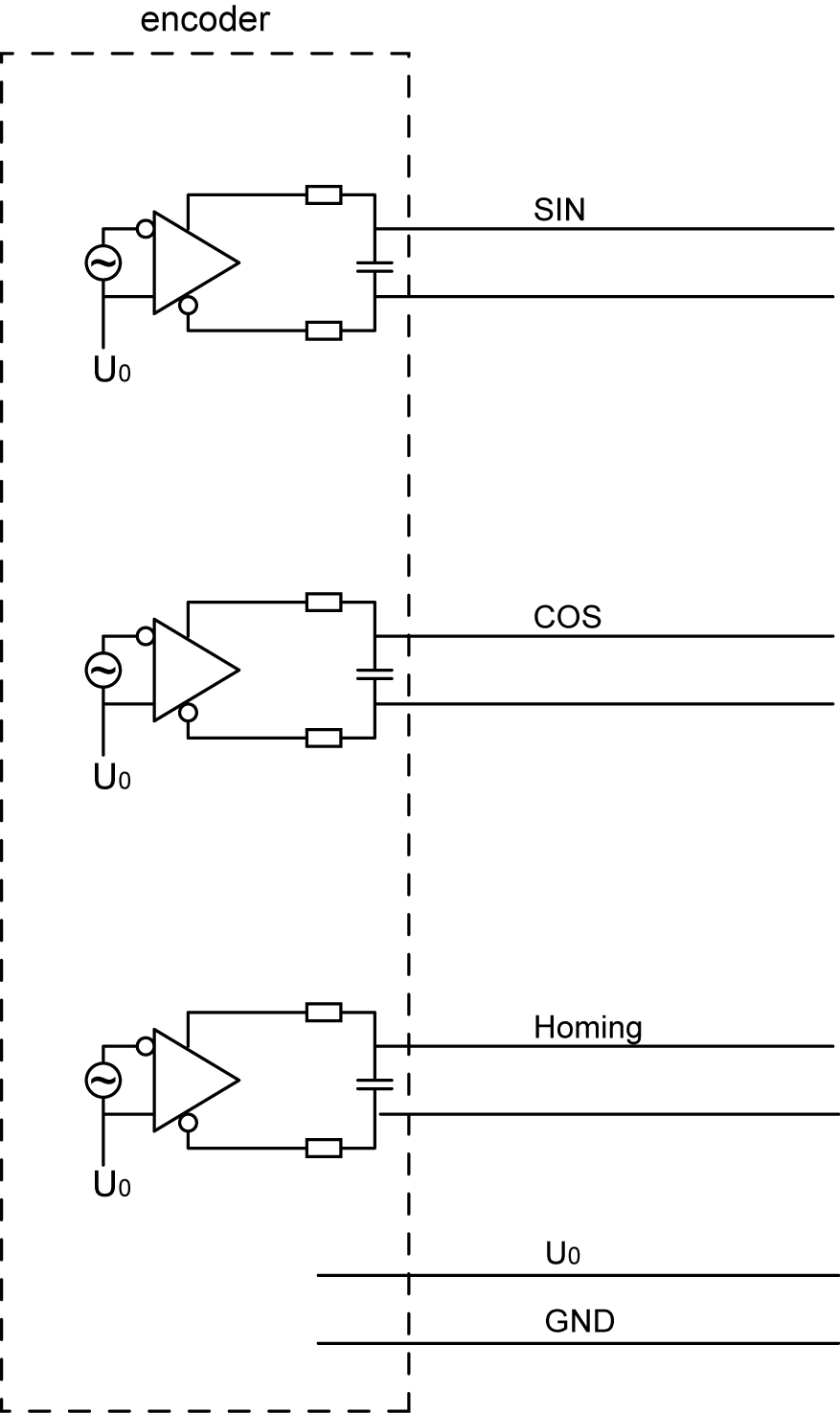
Output circuit