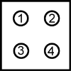
LED status indicator
KE with ACC bus interface
The LED block H1 with four LEDs indicates the status of the compact power supply.
In networked systems the status can also be read on the ACC bus.
|
Status indicator H1 on the front of the device LED 1, 2, 4: green LED 3: red |
|
System ready message (SBM) The compact power supply is supplied with 24 VDC, and has powered up without error but is still not active. The system waits for the control command UE Converter ON. |
|
|
Acknowledgement DC bus ON The control signal UE is active. The DC bus voltage was built up error-free via the mains connection and the charging circuit. |
|
|
|
Feedback ready
Feedback into the grid is ready. |
|
|
|
Diagnostic message Error status (module is disconnected from the grid) LED 3 and combination of LEDs 1, 2 and 4 provide information on error. Siehe 'Behaviour in case of an error'. For information on the diagnostic messages, refer to the document "PDK_025786_Diagnose". |
KE with real-time Ethernet interface

|
H5 | Ethernet bus (link status) |
| H4 | Ethernet bus (link status) | |
| H3 | Bus status | |
| H2 | Feedback | |
| H1 | KE status |
KE without fieldbus interface
The following failures will be indicated by binary outputs and LED signals:
- over-voltage DC bus (no brake resistor, resistance too high)
- short circuit DC bus during loading
- over-temperature heat sink
- over-temperature brake resistor (over-temperature or missing bridge)


