EF individual fuse protection KWD/KWZ
Each module is controlled separately. Acknowledgment signals are available for every module. The power output stage can in this way be blocked and unblocked independent of other modules.
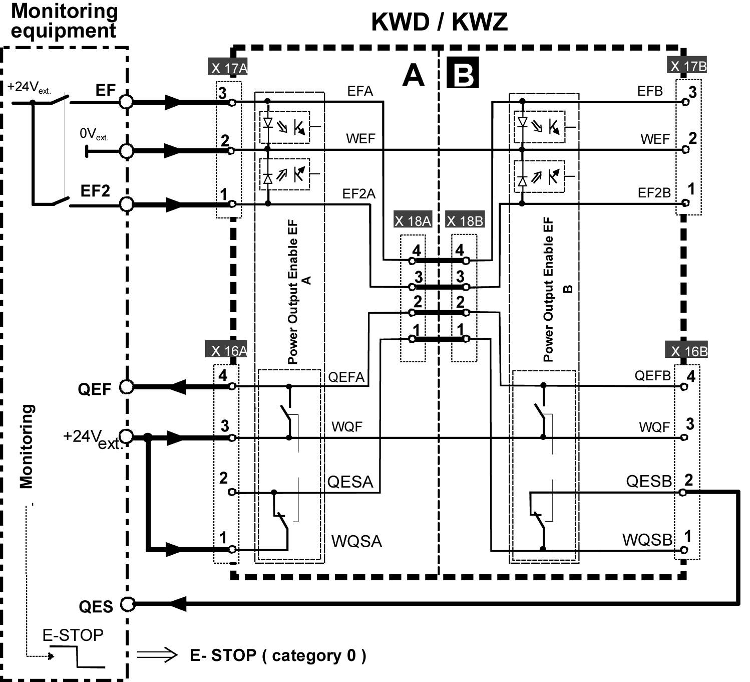
To do so, lay the wiring as described below:
| 24 VDC ext. control signal EF2 | >> | X17A Pin 1 EF2 |
| 0 VDC ext. | >> | X17A Pin 2 WEF |
| 24 VDC ext. control signal EF | >> | X17A Pin 3 EF |
| 24 VDC ext. | >> | X16A Pin 1 WQSA (QESA power supply) |
| X16A Pin 2 | >> | Acknowledgment signal QESA (QESA = 1: Output stage safely blocked) |
| 24 VDC ext. | >> |
X16A Pin 3 WQFA (QEFA power supply) |
| X16A Pin 4 | >> | Acknowledgment signal QEFA (min. 1 EF(2) control signal is set) |
Power output stage enable, one-channel
|
|
The single-channel control of the signals EF and EF2, e.g. by a bridge, is not part of the certification and does not correspond to the safety category PL e according to EN ISO 13849-1. |

If the power output stage enable is only carried by one channel, pin 3 (EF2_x) and pin 4 (EF_x) have to be bridged with individual fuse protection of the drives in connectors 18A and 18B. For group fuse protections, pin 1 ... 4 in connectors 18A and 18B have to be bridged parallel. In the last KWD module of the group, pin 1 and pin 3 in connector 17B have to be bridged.
