Reaction time EF safety function
Response behaviour power output stage
The control signals of the EF safety functions are influenced by an internal hardware and software filter.
An EF/EF2 signal disruption greater than 50 μs affect directly to the hardware The power output stage is immediately locked.
Response behaviour until diagnostic message 2320 'Output stage enabling (EF) inactive with controller enable RF active'
The control signal at the EF/EF2 input is detected in a 1 ms task. An internal error is detected after 10 cycles (10 ms) with low signal. The internal error is evaluated by the EF safety function in a 10 ms task and issued by the system as a diagnostic message 2320.
The diagnostic message according to EF/EF2 (consistent) low signal, is set by the software filter at latest after 20 ms.
Special case input signal EF/EF 2 bounces
The detected high and low signals are buffered with an internal counter (0 - 10). In the case of a bouncing input signal, the counter is reduced by 1 at a high signal. At a low signal the counter increase by 1. If the counter value is 10, an internal error is detected. The internal error is evaluated by the EF safety function in a 10 ms task and issued by the system as a diagnostic message 2320.
Diagrams with constant EF/EF2 signals

|
1) |
Depends on the connected motor |
|
State |
|
||
|---|---|---|---|
|
1 |
The control signal EF/EF2 is deactivated. The power stage is deactivated. SBM = 1, QEF = 0, QES = 1, no diagnostics message
|
||
|
2 |
The control signal EF/EF2 is constantly present. The power stage is released. SBM = 1, QEF = 1, QES = 0, no diagnostics message The motor can be energized by the control signal RF 'controller enable'. |
||
|
3 |
The control signal EF/EF2 is deactivated. The power stage is locked. SBM = 1, QEF = 0, QES = 1, no diagnostics message The hardware acknowledgment signals QEF and QES indicates the safe and torque-free state of the motor. The control signal RF 'Controller enable' is set. SBM is reset and the drive generates the diagnostic message 2320 'EF inactive' with the description 'Output stage enabling (EF) inactive with controller enable RF active'. |

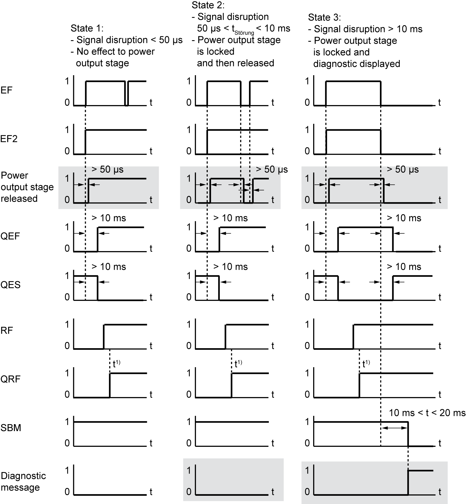
Diagrams with irregular EF/EF2 signals (signal disruption)
|
1) |
Depends on the connected motor |
|
State |
|
||||
|---|---|---|---|---|---|
|
1 |
On the control signal EF/EF2 are signal disruptions of less than 50 μs. The signal disruptions has no effect on the power output stage. SBM = 1, QRF = 1, no diagnostics message |
||||
|
2 |
On the control signal EF/EF2 are approximately 50 µs > signal disruptions < 10 ms available. The power output stage is locked after approximately greater than 50 µs. After the signal disruptions (less than 10 ms), the power stage is released again. The motor is energized. SBM = 1, QRF = 1, no diagnostics message
|
||||
|
3 |
On the control signal EF/EF2 are signal disruptions of more than 10 ms. The power output stage is locked after approximately greater than 50 µs. The hardware acknowledgment signals QEF and QES indicates the torque-free state of the motor (> 10 ms). SBM and QRF is reset and the drive generates the diagnostic message 2320 'EF inactive' with the description 'Output stage enabling (EF) inactive with controller enable RF active'. The diagnostic message according to EF/EF2 (consistent) low signal, is set by the software filter at latest after 20 ms. |
