Switch-on components and mains supply KEN 5(-F, -xN, -S10), KEN 10(-F) and KEN 20-0N
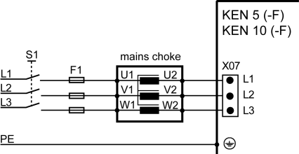
KEN 5(-F) and KEN 10(-F)
Power is supplied to the compact power supply unit via terminal X07.
The main contactor and mains filter are pre-installed on the module. A mains choke is only required for a KEN 10(-F).
After connecting the control signal UE (Converter on) and if the DC bus capacitors are loaded, the KE module closes the integrated main contactor.

|
Module name |
Description |
|
|---|---|---|
|
L1, L2, L3, PE |
Mains supply |
|
|
S1 |
Main contactor | |
|
F1 |
Main fuse |
|
|
Mains choke |
Reduction of induced distortion on the mains and improvement of power factor The compact power supply KEN 5(-F) does not require an external mains choke. |
|
|
X01 -U1 -V1 -W1 |
Mains-side connection -line phase L1 -line phase L2 -line phase L3 |
|
|
X02 -U2 -V2 -W2 |
Load-side connection -line phase L1 -line phase L2 -line phase L3 |
|
|
KEN |
Compact power supply without feedback |
|
|
X07 -L1, L2, L3 |
Mains supply (supply for DC bus) |
|
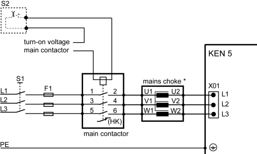
KEN 5-0N and KEN 5-FN
Power is supplied to the compact power supply unit via terminal X01.
The mains filter is pre-installed on the module. A main contactor must be connected externally. A mains choke can optionally be used with a KEN 5-0N.
The switch voltage for the contactor (24V DC or 24V...230V AC, depending on contactor version) must be provided by the user.
The switch voltage for the main contactor is set on the protective conductor.
The DC bus is now directly fed from the line through the main contactor and mains choke.
If necessary, the user can externally interrupt the control of the main contactor (S2), e.g. to separate the drive system power-sided from the line in case of an emergency stop (for further information: Siehe 'Pulse diagram EMERGENCY STOP'.).
The auxiliary contact HK (NC) allows the user to monitor the switch status of the main contactor.
|
Module name |
Description |
|
|---|---|---|
|
L1, L2, L3, PE |
Mains supply |
|
|
S1 |
Main contactor | |
|
F1 |
Main fuse |
|
|
S2 |
If necessary: External safety circuit for main contactor OFF |
|
|
Main contactor |
|
|
|
Main contacts -1 L1 -3 L2 -5 L3 |
Mains-side connection -line phase L1 -line phase L2 -line phase L3 |
|
|
Main contacts -2 T1 -4 T2 -6 T3 |
Load-side connection -line phase L1 -line phase L2 -line phase L3 |
|
|
HK (help contact) |
Option for monitoring switch status |
|
|
Mains choke |
Reduction of induced distortion on the mains and improvement of power factor *Can optionally be used with a KEN 5-0N. |
|
|
X01 -U1 -V1 -W1 |
Mains-side connection -line phase L1 -line phase L2 -line phase L3 |
|
|
X02 -U2 -V2 -W2 |
Load-side connection -line phase L1 -line phase L2 -line phase L3 |
|
|
KEN |
Compact power supply without feedback |
|
|
X01 -L1, L2, L3 |
Mains supply (supply for DC bus) |
|
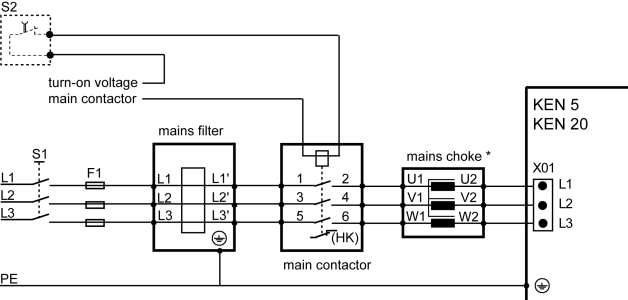
KEN 5-S10 and KEN 20-0N
Power is supplied to the compact power supply unit via terminal X01.
The mains filter is required. The mains choke can optionally be used with a KEN 5-S10. A main contactor must be connected externally.
The switch voltage for the contactor (24V DC or 24V...230V AC, depending on contactor version) must be provided by the user.
The switch voltage for the main contactor is set on the protective conductor.
The DC bus is now directly fed from the line through the main contactor and mains choke.
If necessary, the user can externally interrupt the control of the main contactor (S2), e.g. to separate the drive system power-sided from the line in case of an emergency stop (for further information: Siehe 'Pulse diagram EMERGENCY STOP'.).
The auxiliary contact HK (NC) allows the user to monitor the switch status of the main contactor.

|
Module name |
Description |
|
|---|---|---|
|
L1, L2, L3, PE |
Mains supply |
|
|
S1 |
Main contactor | |
|
F1 |
Main fuse |
|
|
Mains filter |
Compliance with the maximum permissible values for electromagnetic emissions | |
|
X01 -L1 -L2 -L3 |
Mains-side connection -line phase L1 -line phase L2 -line phase L3 |
|
|
X02 -L1' -L2' -L3' |
Load-side connection -line phase L1 -line phase L2 -line phase L3 |
|
|
S2 |
If necessary: External safety circuit for main contactor OFF |
|
|
Main contactor |
|
|
|
Main contacts -1 L1 -3 L2 -5 L3 |
Mains-side connection -line phase L1 -line phase L2 -line phase L3 |
|
|
Main contacts -2 T1 -4 T2 -6 T3 |
Load-side connection -line phase L1 -line phase L2 -line phase L3 |
|
|
HK (help contact) |
Option for monitoring switch status |
|
|
Mains choke |
Reduction of induced distortion on the mains and improvement of power factor *Can optionally be used with a KEN 5-S10. |
|
|
X01 -U1 -V1 -W1 |
Mains-side connection -line phase L1 -line phase L2 -line phase L3 |
|
|
X02 -U2 -V2 -W2 |
Load-side connection -line phase L1 -line phase L2 -line phase L3 |
|
|
KEN |
Compact power supply without feedback |
|
|
X01 -L1, L2, L3 |
Mains supply (supply for DC bus) |
|

