Safely-limited increment (SLI)
Properties
- Safety function according to DIN EN 61800-5-2:2008-04
- Safe monitoring of the parameterisable position range (2-channel)
- Parameterisable stop function in case of error
Description
The safety function can be started by a safe input or by the corresponding bit in the control data.
The acknowledgement can be fed back by safe output or by status data.
The started SLI safety function monitors whether the actual position value of the drive complies with the parametrised range.
The permitted position range results from the actual position at the time when the SLI safety function is selected. The upper position limit is the start position plus the higher value of Prm65 and Prm66. The lower position limit is the start position plus the lower of the two values.
SLI should be combined with SLS or SSR so that the speed is monitored additionally in case of movements within the permitted range of movement.
If this permitted range of movement will be left with a particular speed, the motor is braked via a ramp (see 'Reaction in case of an error') if SS1 or SS2 are parameterised as error reaction. Because of this delay, the drive runs further into the not permitted range.
This transition range up to standstill has to be taken into account when fixing the permitted range of movement. The transition range is not monitored by the SLI safety function
|
|
The resolution of the position is standardised to 65536 increments/revolution. |

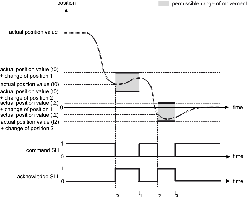
Example 1: Drive movement in the permissible range of movement
|
Time t |
Explanation |
|---|---|
|
t = t0 |
The safety function is started and the SLI acknowledgement bit is set. |
|
t0 < t < t1 |
The safety function monitors whether the actual position value meets the position limits. |
|
t = t1 |
The safety function is deactivated and the SLI acknowledgement bit is reset. |
|
t1< t < t2 |
No monitoring by the SLI safety function is active. |
|
t = t2 |
The safety function is started and the SLI acknowledgement bit is set. |
|
t2 < t < t3 |
The safety function monitors whether the actual position value meets the position limits. |
|
t = t3 |
The safety function is deactivated and the SLI acknowledgement bit is reset. |
|
t > t3 |
No monitoring by the SLI safety function is active. |
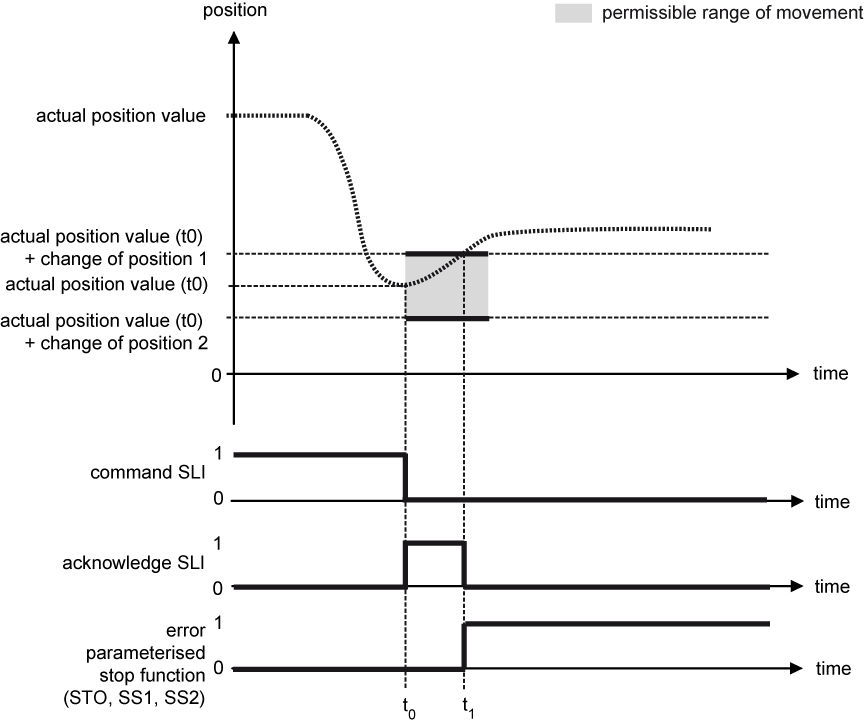
As soon as the safety function detects a deviation from the limits of the monitored values, the drive executes a safe stop function that has previously been set by parameter ('Safe torque off (STO)', 'Safe stop 1 (SS1)' or 'Safe stop 2 (SS2)') (example 2).
|
|
|
|
|
Danger to life due to unexpected movements! The drive will be torque-free in the status 'Safe torque off (STO)', in case of mains failure or in case of faulty drive controller. External application of force on the drive axis may result in life-threatening movements (e.g. hanging axes can fall down). Steps to prevent:
|


|
|
|
|
|
Danger due to unexpected stop function! If there are different error reactions projected for the safety functions, an unexpected final state can occur in case of error. Example: Steps to prevent:
|
Example 2: Deviation from the permissible position range
|
Time t |
Explanation |
|---|---|
|
t = t0 |
The safety function is started and the SLI acknowledgement bit is set. |
|
t0 < t < t1 |
The safety function monitors whether the position feedback value meets the position limits. |
|
t = t1 |
The safety function detects an error, starts the parameterised stop function and sets the error bit. The SLI acknowledgement bit is reset. |
|
t > t1 |
The behaviour is dependant on the parameterised stop function. |
Acknowledge an error with "Clear error"
As soon as an active safety function detects a deviation from the limits of the monitored values, the drive is set to the intended stop function. The error bit (FSoE status bit 7) is set and the acknowledgment of the safe status is withdrawn.
With the 'Clear error' signal (FSoE control bit 7 or the 'Clear error' command in the drive controller) the
error status ist acknowledged (deleted). If during and after the 'Clear error' the start signal from a previous safety function is still active and no other changes to the settings of the safety function have been made, the safety function restarts and also transition times (if available) work again.
Parameters
Safe parameters
|
Parameter |
Name |
Code |
Unit |
Min |
Max |
|
'SLI Safely limited position change 1' |
S(ul,SLI) |
Incr. |
-2147483647 |
2147483647 |
|
'SLI Safely limited position change 2' |
S(ll,SLI) |
Incr. |
-2147483647 |
2147483647 |
|
'SLI error reaction' |
SLI_ERR |
- |
0 |
2 |
|
|
The values of the position limits Prm65 / Prm66 must be entered appropriately signed. Example: Prm65 = 1000, Prm66 = -100, actual position value (t0) = 10000 increments => monitored range 9900 ... 11000 increments |
|
|
It is the responsibility of the user to enter reasonable values. |
