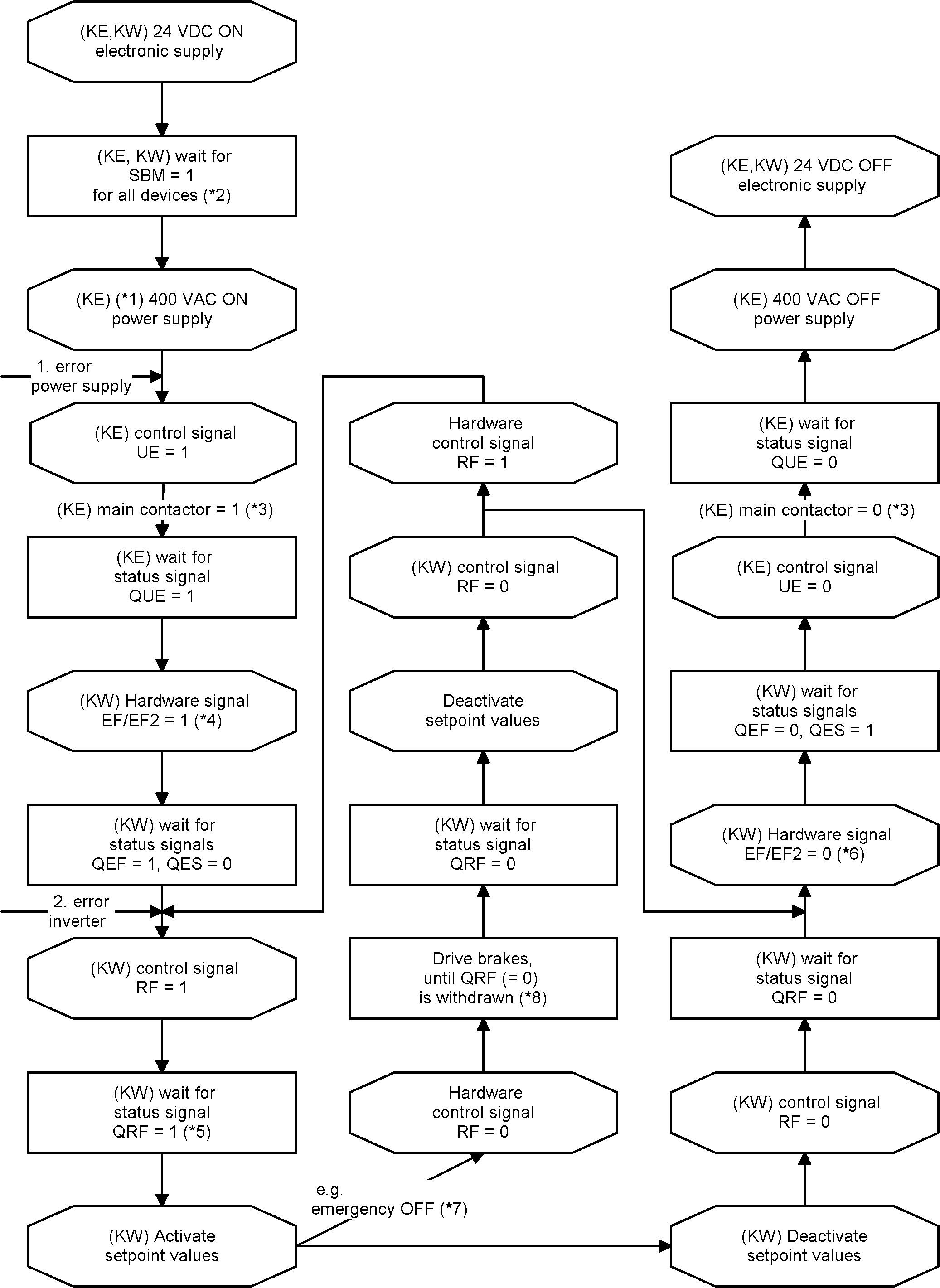
Switch-on and -off flow chart
|
*1 |
Close emergency OFF circuit (if existent). |
| *2 |
The module specific 'System ready' messages (SBM = 1) from the KE and KW modules signal the error-free states. |
| *3 |
If present, the required external main contactor is actuated by the KE. The delay time until the contactor is actuated via terminal X20 (EH1/EH2) depends on the DC bus capacities connected to the KE. |
| *4 |
Only devices with EF logic: Hardware signal EF/EF2 must be applied at the latest at that time. |
| *5 |
Delay time until QRF is set depends on the connected motor resp. whether the data set must be newly calculated because of a modification of drive specific parameters. |
| *6 |
Only devices with EF logic: Reset hardware signal EF/EF2 if the motor has to be in a safe torque-free state afterwards. |
|
*7 |
RF will be disabled via BE. BE is linked with PLC signal, see ID32796 'Source RF'. |
|
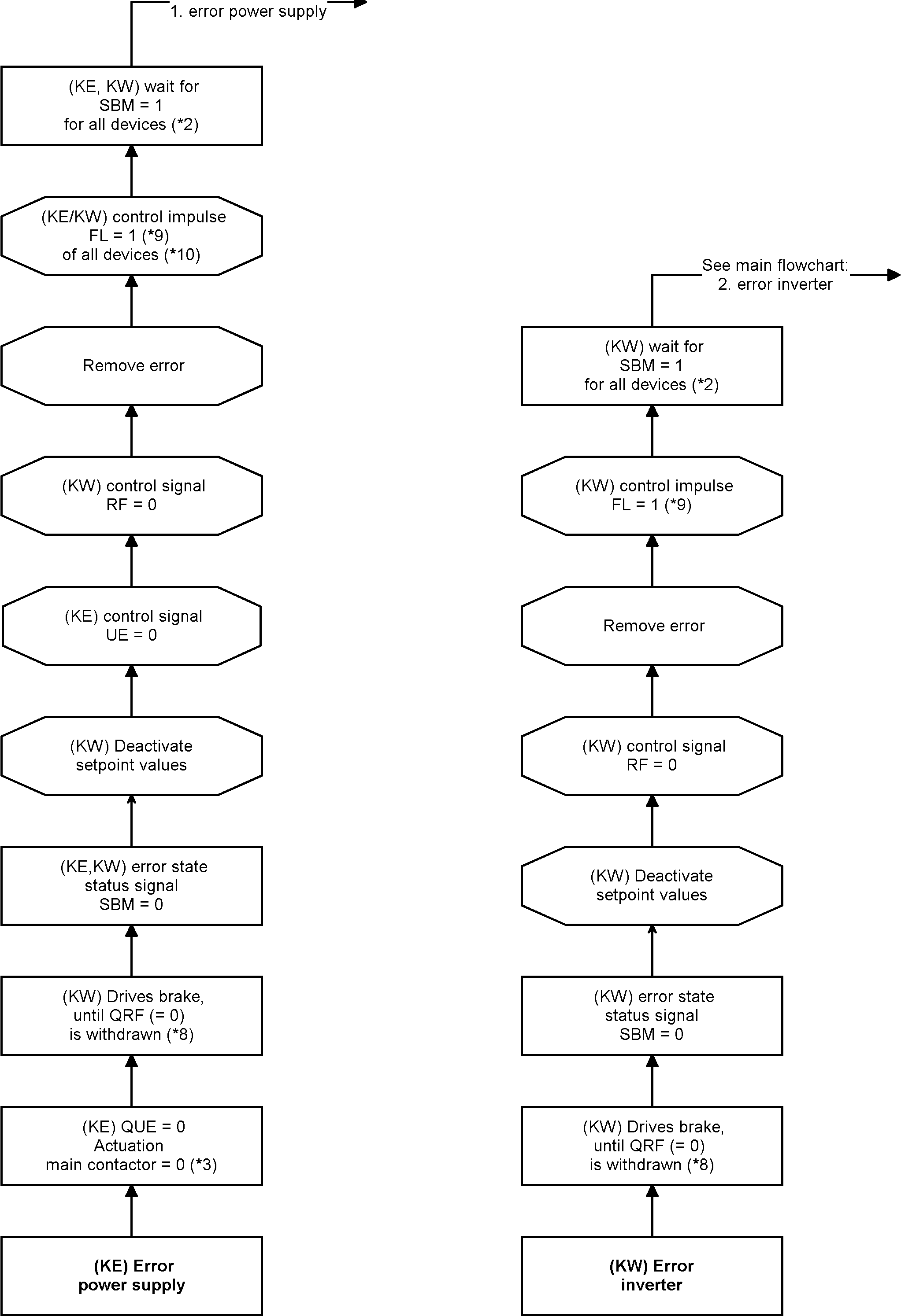
*8 |
Motor is braked to a standstill after the ramp ID32782 'Deceleration ramp RF inactive'. |
| *9 | Pulse ≥ 1 ms. |
| *10 |
Each inverter generated a DC bus error. |
Explanation of the status and control signals: Siehe 'Status and control signals'.
|
|
KW-R07 / -R17 For the machine startup of a controller card with functional safety, the safety functions must be de-activated. Therefore, the safe inputs must be connected stringently, and the SafePMT parameter set must be adapted. Without these adaptations, the startup of a servo motor is not possible. See document 'Safety manual; functional safety' (Part no. 203446), chapter 'Running KW-R07 / -R17 |

