[X130] resolver
Description
This connection supports following encoder types: R
Technical data
- Maximum encoder line length: 100 m
Design
|
Type |
Poles |
Class |
|---|---|---|
|
D-SUB |
9 |
Socket |
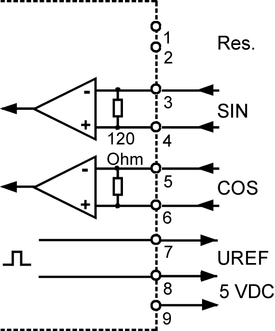
Assignment
|
[X130] |
Connection |
Signal |
|---|---|---|
|
front view, device side
|
1 |
- |
|
2 |
- |
|
|
3 |
+SIN |
|
|
4 |
-SIN |
|
|
5 |
+COS | |
|
6 |
-COS | |
|
7 |
+UREF |
|
| 8 | -UREF | |
| 9 |
|

Connection
|
Cable |
4 x 2 x 0.25 mm2 twisted pair + 4 x 0.5 mm2 shielded |
|
Shield connection |
Shield on both sides |
|
Cable assembly |
D-SUB connector 9-pin with metalized housing |
|
Note |
The shield of the cable has to be grounded by the screw connection in the plug housing on the motor side. The shield mesh is everted over the terminal insert. After screwing together, the shield is placed over the contact spring and the plug housing on the mass. |
Controller input circuit
| Encoder evaluation according ID32953 |
R-encoder |
|
|---|---|---|
| Data | Units |
Resolver |
|
Excitation signal |
||
| Primary voltage |
VDC |
6 ±8 % |
|
Input current without load |
mA |
max. 75 |
| Frequency [kHz] |
kHz |
8 |
|
Output signals |
||
| Transmission ratio |
|
0.5 ±5 % |
| Number of pole pairs 1) |
|
1 |
| Output voltage |
VSS |
1 - 1.8 |
| 1) | Resolvers / Hall encoders with one pole pair are exclusively permitted! |
| Resolver | |
|---|---|
|
|

Encoder signal evaluation
In ID32953 'Encoder type' is defined how to evaluate the incoming encoder signals.
