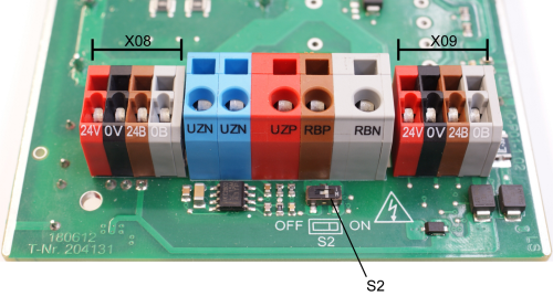
iC: [X08 / X09] 24 VDC supply voltage - Transmission
|
NOTE |
|
|---|---|
| Material damage! |
Material damage due to overvoltage! An overvoltage at the connections X08 and X09 (24 VDC) is not monitored and damages the device Steps to prevent:
|
Description:
X08: 24 VDC supply voltage supply line for electronics and STO / motor holding brake
X09: 24 VDC supply voltage transmission for electronics and STO / motor holding brake
External power supply units that provides the 24 VDC supply voltage for connections 24V and they must have a "safe isolation" (PELV) according to EN 61800-5-1. The 0 V potential must be connected with PE. The current of the 24V and supply must be limited to
A power supply unit is integrated into the that supplies the 24 VDC from the DC bus for the electronics supply. The power supply unit is active when the SMD-DIP switch S2 is in the "ON" switch setting (delivery status for devices with an integrated power supply unit).
|
|
Significant prerequisite for certification of a machine with functional safety: When using the functional safety the internal power supply unit must be deactivated (S2 = OFF), and the 24 VDC (for connections 24V and ) is provided externally with a PELV power supply, otherwise the conditions for the use of functional safety are not satisfied! |
In the event of a failure of the 24 VDC supply to the electronics > 10 ms, the system ready message is internally reset.
|
Switch off the internal 24 VDC supply voltage from the DC bus with the switch S2
|
|||||
|
|||||
|
The S2 switch is located in the |
|||||
Wiring for STO safety function according to EN 61800-5-2
|
|
Switch off the internal 24 VDC supply voltage from the DC bus with the switch S2 |
According to EN 61800-5-2 the error 'Short circuit between two conductors' will be excluded in the following cases:
- For permanently connected conductors which are protected from external damage (e.g. cable channel)
- Different sheathed cables (e.g. separate cables at iC for 24B / 0B and 24V / 0V)
- Inside an electrical installation space
- The conductors are separately screened and have a earth connection
Technical data
24 VDC supply voltage:
- 24 VDC ± 15% PELV power supply acc. to IEC/EN 60950
- Ripple max. 5%, with integrated switch-on current limitation
- The 0 V potential of the power supply unit should be earthed at the central PE
Design
|
Type |
Pole |
Sort |
Manufacturer |
Designation |
|---|---|---|---|---|
|
Terminal with tension spring connection |
4 |
|
WAGO |
739 |
Actuating tool: Screwdriver with a blade 2.5 x 0.4 mm
The cable is attached to the housing: Cable gland M25 x 1.5
Assignment
|
[X08] |
Signal |
Description |
|||||
|---|---|---|---|---|---|---|---|
|
24V 1) |
24 VDC supply voltage |
||||||
|
0V |
Reference potential for 24 VDC |
||||||
|
24B 1) |
Supply voltage 24 VDC
The supply voltage directly controls the STO state and at the same time supplies an optional motor holding brake with power. |
||||||
|
0B |
Reference potential for 24B / transmission |
|
1) |
The current of the 24V |
|
[X09] |
Signal |
Description |
|---|---|---|
|
24V 1) |
24 VDC transmission |
|
|
0V |
Reference potential for 24 VDC |
|
|
24B 1) |
24 VDC transmission |
|
|
0B |
Reference potential for 24B |
|
1) |
Please refer to the device description of the connected device for the pin assignment |
Connection
|
Cable |
4 x 0.5 mm2 / AWG 20, shielded |
|
Max. conductor cross-section of the terminal |
Flexible cable with a wire end sleeve with plastic collar: 1 mm2 |
|
Stripping length |
5 - 6 mm |
|
Shield connection |
Apply on both sides |


