Safe stop 2 (SS2)
Properties
- Safety function according to DIN EN 61800-5-2:2008-04
- Controlled stop according to EN 60204-1, stop category 2
- Safe standstill control with drift recognition
(2-channel monitoring of the actual speed and position values)
Description
The safety function is started by the corresponding bit in the control data.
The acknowledgement is fed back by status data.
The initialised SS2 safety function monitors the deceleration process of the drive and subsequently the safe standstill in regular operations. The deceleration procedure must be initiated by the user controller.
|
|
|
|
|
Danger to life due to unexpected movements! The normal operating function 'Safe encoder monitoring (SEM)' is active at any time. In the status 'Safe torque off (STO)', in case of mains failure or defective drive controller, the drive will be torque-free. External force applied to the drive axis can cause life-threatening movements, e.g. hanging axes can fall down. Steps to prevent:
|


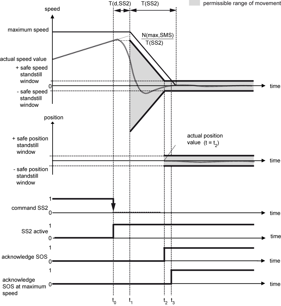
Example 1: Drive movement in the permissible range of movement
|
Time t |
Explanation |
|---|---|
|
t = t0 |
The safety function is started by a 1-0 edge and cannot be interrupted. |
|
t0 < t < t1 |
During the transition period, the actual speed value of the drive must be adjusted to the parameterised limits of the started safety function. The parameterised limits are not monitored yet. |
|
t1 ≤ t < t2 |
The safety function monitors the parameterised ramp and checks whether the actual speed value meets the permissible range of movement. |
|
t ≥ t2 |
The safety function switches the drive into the SOS state and sets the SOS acknowledgement bit. |
|
t = t3 |
SOS acknowledgement at maximum speed |
Reaction in case of an error
As soon as the safety function detects a deviation from the limits of the monitored values, the drive is set to the safe state 'Safe torque off (STO)' (example 2) and (example 3).
|
|
|
|
|
Danger to life due to unexpected movements! The drive will be torque-free in the status 'Safe torque off (STO)', in case of mains failure or in case of faulty drive controller. External application of force on the drive axis may result in life-threatening movements (e.g. hanging axes can fall down). Steps to prevent:
|
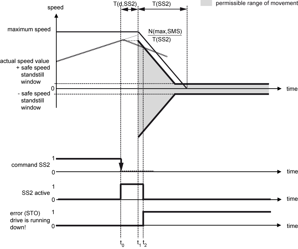
Example 2: Drive movement deviates from the parameterised deceleration ramp
|
Time t |
Explanation |
|---|---|
|
t = t0 |
The safety function is started by a 1-0 edge and cannot be interrupted. |
|
t0 < t < t1 |
During the transition period, the actual speed value of the drive must be adjusted to the parameterised limits of the started safety function. The parameterised limits are not monitored yet. |
|
t1 ≤ t < t2 |
The safety function monitors the parameterised ramp and checks whether the actual speed value meets the permissible range of movement. |
|
t = t2 |
The safety function detects an error, switches the drive into the STO state and sets the error bit. |
|
t ≥ t2 |
In the STO state, drive movements are no longer monitored since no further error reaction is possible. |
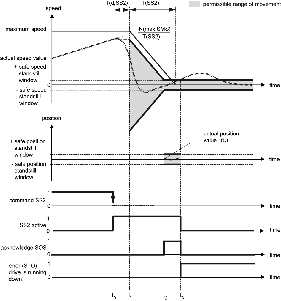
Example 3: Drive movement deviates from the safe speed standstill window in the SOS state
|
Time t |
Explanation |
|---|---|
|
t = t0 |
The safety function is started by a 1-0 edge and cannot be interrupted. |
|
t0 < t < t1 |
During the transition period, the actual speed value of the drive must be adjusted to the parameterised limits of the started safety function. The parameterised limits are not monitored yet. |
|
t1 ≤ t < t2 |
The safety function monitors the parameterised ramp and checks whether the actual speed value meets the permissible range of movement. |
|
t = t2 |
The safety function switches the drive into the SOS state and sets the SOS acknowledgement bit. |
|
t2 ≤ t < t3 |
In the SOS state, the safety function monitors whether the actual speed value is in the safe speed standstill window and the actual position value complies with the safe position standstill window. |
|
t = t3 |
The safety function detects an error, switches the drive into the STO state and sets the error bit. The SOS acknowledgement bit is reset. |
|
t ≥ t3 |
In the STO state, drive movements are no longer monitored since no further error reaction is possible. |
Acknowledge an error with "Clear error"
As soon as an active safety function detects a deviation from the limits of the monitored values, the drive is set to the intended stop function. The error bit (FSoE status bit 7) is set and the acknowledgment of the safe status is withdrawn.
With the 'Clear error' signal (FSoE control bit 7 or the 'Clear error' command in the drive controller) the
error status ist acknowledged (deleted). If during and after the 'Clear error' the start signal from a previous safety function is still active and no other changes to the settings of the safety function have been made, the safety function restarts and also transition times (if available) work again.
Parameters
Safe parameters
|
Parameter |
Name |
Code |
Unit |
Min |
Max |
|
'SS2 transition period' |
T(d,SS2) |
ms |
0 |
65535 |
|
'SS2 brake ramp time' |
T(SS2) |
ms |
0 |
65535 |
|
'SS2 safe speed standstill window' |
N(zero,SS2) |
U/min |
0 |
60000 |
|
'SS2 safe position standstill window' |
S(zero,SS2) |
Incr. |
-2147483647 |
2147483647 |
|
'SMS safe maximum speed' |
N(max,SMS) |
rpm |
0 |
60000 |
