'State machine' diagram
The following diagram shows the correlation between the object 0x6040 'Control word' and object 0x6041 'Status word' and the equivalent AMK control and status messages. The diagram is derived of the 'State machine' described in the standard CiA DSP 402.
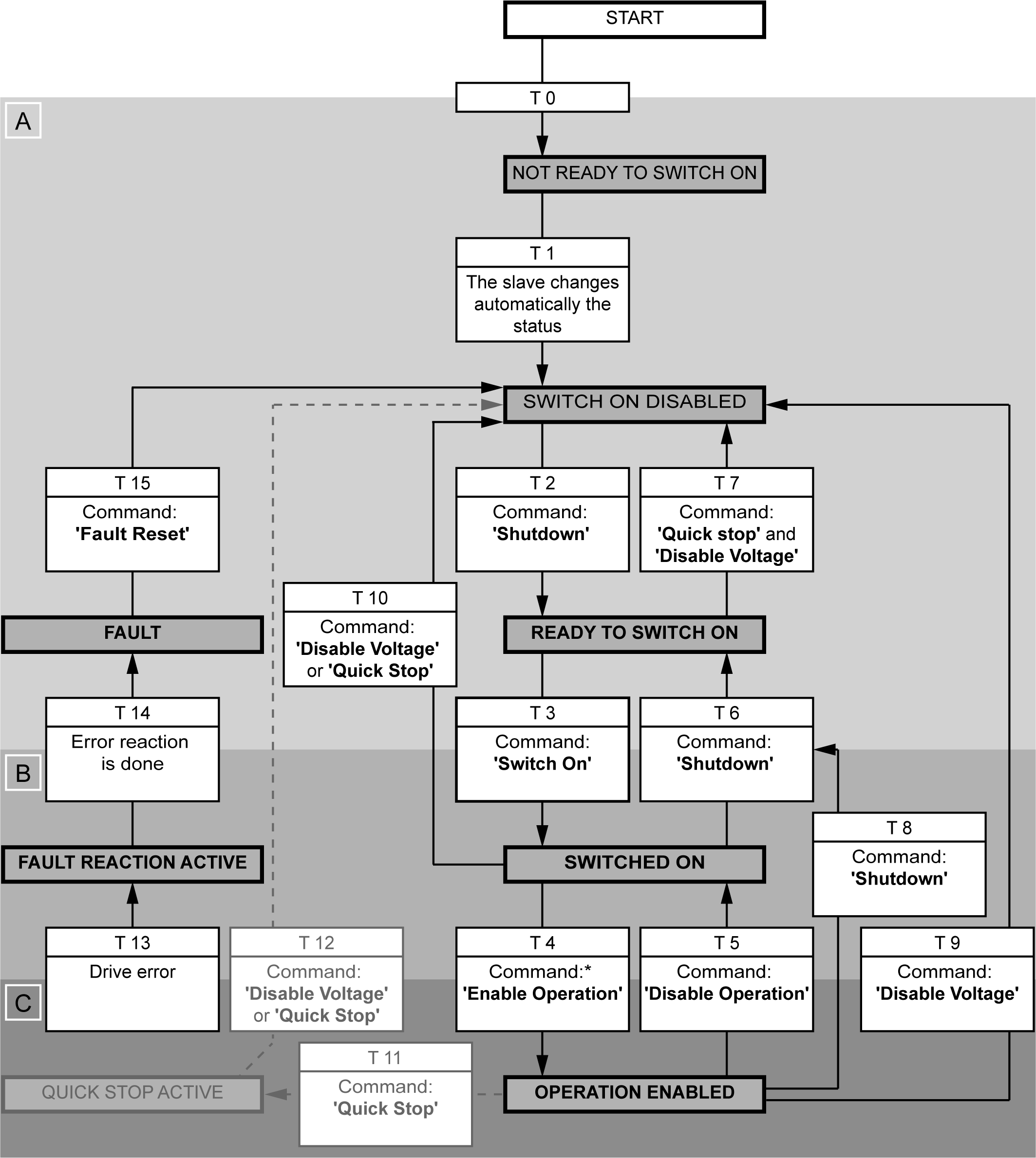
Legend:
|
States in [bold] |
The acknowledgment of these states must be monitored by the master |
| States in [normal] |
The slave uses these states independently |
|
T x |
Transition / state transition |
|
* |
Prerequisites for the 'Enable Operation' command: Object 0x221F 'Source RF' = 5 alternative Object 0x221F 'Source RF' = 25 |
|
A |
Low-level power: Electronic supply available |
|
B |
High-level power: Power supply DC bus available |
|
C |
Torque: Power output stage enabled and motor is energized |
Further notes:
- The 'State Machine' is executed in 1 ms cycle time.
- Drive is braking according to
- The transition 11 and 12 and the command 'Quick Stop' are not supported.
