Overview of application parameters (Index)
|
Index |
Designation |
Effective in |
Default value |
Unit 2) |
Data type |
Meaning |
|---|---|---|---|---|---|---|
| 1001 | ‘Software limit switch position positive’ | Position | 0 | Incr | LREAL (8) | |
| 1002 | ‘Software limit switch position negative’ | Position | 0 |
Incr |
LREAL (8) |
|
| 1003 | ‘Acceleration’ | Position | 16666,66667 |
0.001 rev/s2 |
LREAL (8) | |
| 1004 | ‘Deceleration’ | Position | 16666,66667 | 0.001 rev/s2 | LREAL (8) | |
| 1005 | ‘Acceleration jerk’ | Position | 166666,6667 | 0.001 rev/s3 | LREAL (8) | |
| 1006 | ‘Deceleration jerk’ | Position | 166666,6667 | 0.001 rev/s3 | LREAL (8) | |
| 1007 | ‘Emergency Stop ramp deceleration’ | Position | 0 | 0.001 rev/s2 | LREAL (8) | |
| 1008 | ‘Emergency Stop ramp deceleration jerk’ | Position | 0 | 0.001 rev/s3 | LREAL (8) | |
| 1009 | 'Torque threshold (positioning to fixed stop)' | Position | 1000 |
0.1% MN |
INT (2) | |
| 1010 | ‘Time to fixed stop’ | Position | 10 |
0.001 s |
DINT (4) | |
| 1011 | 'Switching position (positioning to fixed stop)' | Position | 0 | Incr | DINT (4) | Switching position is relative to target position |
| 1012 | 'Switching velocity (positioning to fixed stop)' | Position | 0 | 0.0001 rpm | LREAL (8) | Velocity from the switching position |
| 1013 | ‘Window in position positive’ | Position | 1000 | Incr | DINT (4) | |
| 1014 | ‘Window in position negative’ | Position | 1000 | Incr | DINT (4) | |
| 1100 | ‘Speed ramp active’ | Speed | 1 | - | BOOL (1) |
0: inactive 1: active |
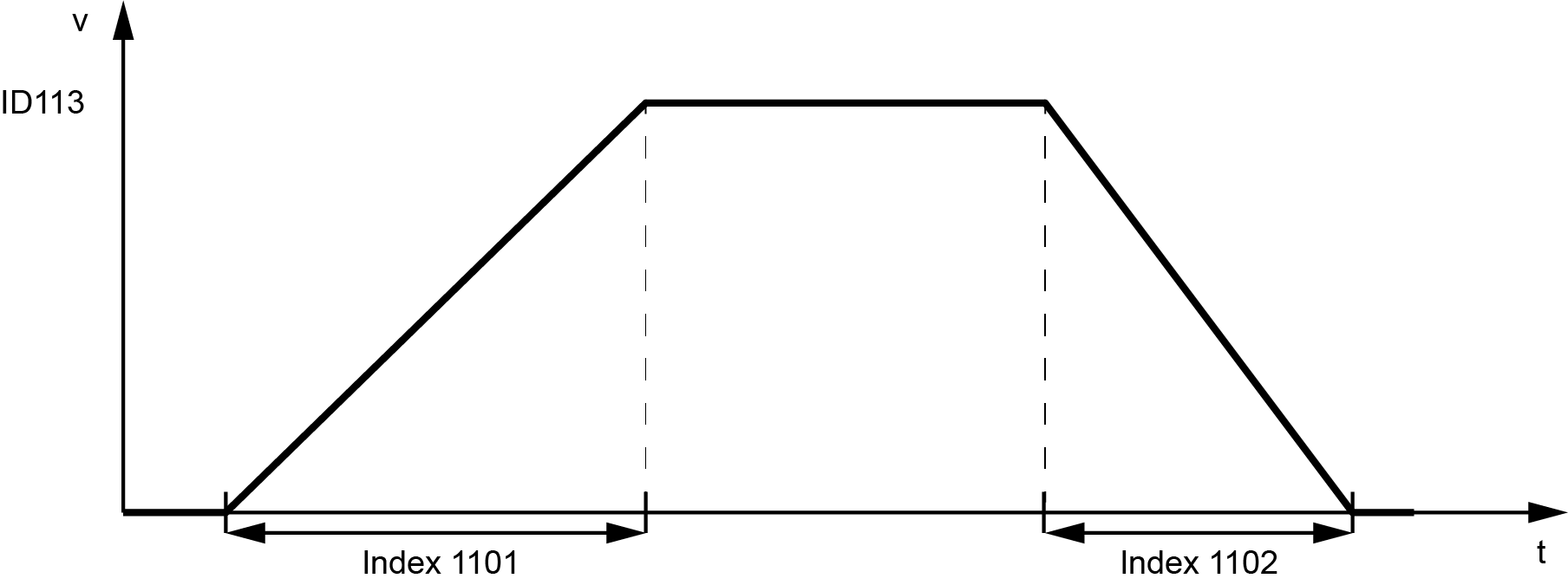
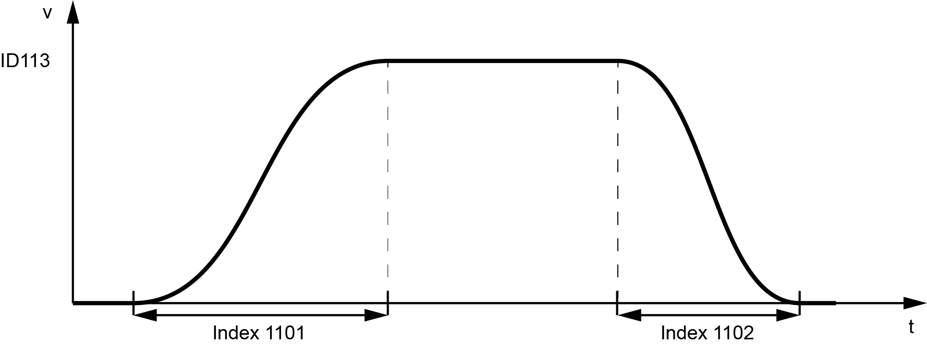
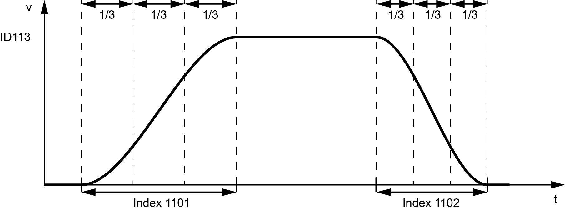
| 1101 | ‘Speed ramp positive’ | Speed | 1000 | 0.001 s | DINT (4) | 3) |
| 1102 | ‘Speed ramp negative’ | Speed | 1000 |
0.001 s |
DINT (4) | 3) |
| 1103 | ‘Speed ramp emergency stop’ | Speed | 100 | 0.001 s | DINT (4) | |
| 1104 | ‘Speed ramp type’ | Speed |
2 |
- | DINT (4) |
0: linear 3) 1: S ramp 4) 2: trapezoidal 5) |
|
1105 |
'Jerk acceleration' |
Speed |
100 |
0.001 rev/s3 |
LREAL (8) |
|
|
1106 |
'Jerk decelleration' |
Speed |
100 |
0.001 rev/s3 |
LREAL (8) |
|
|
1107 |
'Jerk Emergency Stop' |
Speed |
10 |
0.001 rev/s3 |
LREAL (8) |
|
|
1108 |
'Speed window' |
Speed |
50000,0 |
0.0001 rpm |
LREAL (8) |
|
| 1200 | ‘Activate timeout’ | Global | 0 | - | BOOL (1) |
0: inactive 1: active |
| 1201 | ‘Timeout time’ | Global |
1000 |
0.001 s | DINT (4) | |
| 1300 | ‘Minimum command time’ | Global | 1 | 0.001 s | DINT (4) | |
| 1400 | ‘Reversal of direction of rotation’ | Scaling | 0 | - | BOOL (1) |
0: direction of rotation clockwise, looking at the motor shaft 1: direction of rotation counterclockwise, looking at the motor shaft |
| 1401 | ‘Gear(box) multiplier’ | Scaling | 1.0 | - | LREAL (8) | |
| 1402 | ‘Gear(box) divisor’ | Scaling | 1.0 | - | LREAL (8) | |
| 1403 | ‘Feed constant’ | Scaling | ID1161) | - | LREAL (8) | |
| 1404 | ‘Speed scaling multiplier’ | Scaling | ID1161) | - | LREAL (8) | |
| 1405 | ‘Speed scaling divisor’ | Scaling | 1.0 | - | LREAL (8) | |
| 1406 | ‘Position scaling multiplier’ | Scaling | 1.0 | - | LREAL (8) | |
| 1407 | ‘Position scaling divisor’ | Scaling | 1.0 | - | LREAL (8) | |
| 1408 | ‘Torque scaling multiplier’ | Scaling | 1.0 | - | LREAL (8) | |
| 1409 | ‘Torque scaling divisor’ | Scaling | 1.0 | - | LREAL (8) | |
| 1410 | ‘Acceleration scaling multiplier’ | Scaling | ID1161) | - | LREAL (8) | |
| 1411 | ‘Acceleration scaling divisor’ | Scaling | 1.0 | - | LREAL (8) | |
| 1412 | ‘Jerk scaling multiplier’ | Scaling | ID1161) | - | LREAL (8) | |
| 1413 | ‘Jerk scaling divisor’ | Scaling | 1.0 | - | LREAL (8) | |
| 1500 | ‘Cycle counter’ | Global | 0 |
|
DINT (4) | |
| 1501 | ‘Motor serial number configured’ | Global | 0 | DINT (4) | ||
| 1502 | ‘Device serial number configured’ | Global | 0 | DINT (4) | ||
| 1503 | ‘Motor serial number monitoring’ | Global | 0 | BOOL (1) |
0: inactive 1: active |
|
| 1504 | ‘Device serial number monitoring’ | Global | 0 | BOOL (1) |
0: inactive 1: active |
|
| 1550 | 'Torque limit positve' | Global | Value from ID82 | 0,1 %MN | LREAL (8) | |
| 1551 | 'Torque limit negative' | Global | Value from ID83 | 0,1 %MN | LREAL (8) | |
| 1552 | 'Speed limit positive' | Global | Value from ID38 | 0.0001 rpm | LREAL (8) | |
| 1553 | 'Speed limit negative' | Global | Value from ID39 | 0.0001 rpm | LREAL (8) |
|
1) |
If no value is defined, AFI uses the value from ID116 in the basic system. |
| 2) | Scaling is valid for the default setting of the scaling parameters. |
| 3) |
|
| 4) |
|
| 5) |
|
