Mode 'Free CAN message configuration'
In 'Free CAN message configuration' mode, the data exchange between inverter and CAN control can be freely configured by the user.
When configuring, note that the maximum data length of 8 bytes is maintained and the transmission rate is sufficient for the selected transmission cycles.
Characteristics:
-
CAN 2.0 A bus supports the 11-bit identifier format ('base frame format')
-
Any CAN identifier
- Transmission in Intel format
-
Up to 10 send messages which can contain up to 10 signals
- Up to 10 receive messages each containing up to 10 signals
- Transmission of SONDER signals: Siehe 'Special Signals'.
- Transmission of SERCOS parameters: Siehe 'SERCOS parameter'.
-
Limitation data range of a signal
- Cyclic transmission, variable output rates in 1 ms steps
- Event-controlled transmission, variable delay time in 1 ms steps
-
Variable transfer rate
-
Inverted control signal for the plausibility check of setpoints and actual values
- Telegram failure monitoring
-
Message counter
-
Checksum
The message configuration is configured with ID34091 'User list 3' application specific.
Structure ID34091 'User list 3':
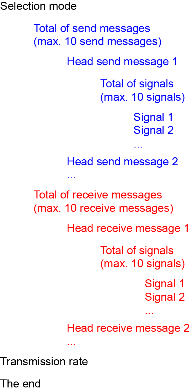
Detailed structure ID34091 'User list 3'
|
|
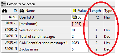
The configuration values must be entered ascending in the list elements of ID34091 'User list 3'. No values may be omitted. The default length of a list item is 2 bytes. For 1 byte values, the length must be adjusted manually. |

|
Configuration |
Data value |
Meaning |
|---|---|---|
|
Selection mode |
UNS08 (1 byte) |
The 'Free CAN message configuration' is activated with the value 0x01. |
|
Send messages |
Data value |
Meaning |
||||||||||||||||||||
|---|---|---|---|---|---|---|---|---|---|---|---|---|---|---|---|---|---|---|---|---|---|---|
|
|
UNS08 (1 byte) |
Total of send messages (max. 10 send messages) |
||||||||||||||||||||
|
Head send |
UNS16 (2 byte)
|
CAN Identifier send messages 1 |
||||||||||||||||||||
|
|
||||||||||||||||||||||
|
|
UNS16 (2 byte)
|
Cycle
See 'Send message attribute' |
||||||||||||||||||||
|
|
||||||||||||||||||||||
|
|
UNS08 (1 byte) |
Data length The data length is the sum of the configured signals. Possible data length 1 .. 8 bytes.
Example: Signal 1: 1 byte Signal 2: 1 byte Signal 3: 2 byte Data length message 1 = 4 byte
Specifying the exact data length reduces the bus load. |
||||||||||||||||||||
|
|
UNS08 (1 byte) |
Attribute send message Setting of message properties
|
||||||||||||||||||||
|
|
UNS08 (1 byte) |
Total of signals Up to 10 signals with a total data length of 8 bytes in a send message.
|
||||||||||||||||||||
|
Configuration signal 1 of the send message 1
|
UNS08 (1 byte) |
Signal type The signal type determines if the following signal ('Index') is a 'SERCOS parameter' or 'Special signal'.
|
||||||||||||||||||||
|
|
UNS08 (1 byte) |
Reserved: Only value 0 is allowed. |
||||||||||||||||||||
|
|
UNS16 (2 byte)
|
Index Signal number 1 of the send message 1
|
||||||||||||||||||||
|
|
||||||||||||||||||||||
|
|
UNS08 (1 byte) |
Length in bits The data length of a signal can be limited by specifying 'Length in bits'.
Example: Signal data length bbbb aaaa (1 byte). User data bit 0..3 'Length in bits' = 4 Transmitted value: aaaa
With 'Attribute send signal bit 2' , you can set if the higher-order bits are omitted or the signal is limited to the maximum displayable value. |
||||||||||||||||||||
|
|
UNS08 (1 byte) |
Shift in bits 2) The entered value is used to specify the start bit of the signal in the message. (0..63 bit)
Example: 3 Signals in a send message Signal 1; size 1 byte: shift in bit = 0 Signal 2; size 2 byte: shift in bit = 8 Signal 3; size 1 byte: shift in bit = 24 |
||||||||||||||||||||
|
|
UNS08 (1 byte) |
Attribute send signal Setting of the signal characteristics
|
||||||||||||||||||||
|
Configuration signal 2 of the send message 1 |
|
|
|
Receive message |
Data value |
Meaning |
||||||||
|---|---|---|---|---|---|---|---|---|---|---|
|
|
UNS08 (1 byte) |
Total of receive messages (max. 10 receive messages) |
||||||||
|
Head receive message 1
|
UNS16 (2 byte)
|
CAN Identifier receive message 1 |
||||||||
|
UNS16 (2 byte)
|
Telegram failure monitoring 3) Error message in case of failure of the message, after the specified time in ms; 0 = no monitoring |
|||||||||
|
UNS08 (1 byte) |
Data length The data length is the sum of the configured signals. Possible data length 1 .. 8 bytes.
Example: Signal 1: 1 byte Signal 2: 1 byte Signal 3: 2 byte Data length message 1 = 4 byte
Specifying the exact data length reduces the bus load. |
|||||||||
|
UNS08 (1 byte) |
Attribute receive message Only value 0 is allowed. |
|||||||||
|
|
UNS08 (1 byte) |
Total of signals Up to 10 signals with a total data length of 8 bytes in a receive message.
|
||||||||
|
Configuration signal 1 of the receive message |
UNS08 (1 byte) |
Signal type The signal type determines if the following signal ('Index') is a 'SERCOS parameter' or 'Special signal'.
|
||||||||
|
|
UNS08 (1 byte) |
Reserved: Only value 0 is allowed. |
||||||||
|
|
UNS16 (2 byte)
|
Index Signal number 1 of the send message 1
|
||||||||
|
|
||||||||||
|
|
UNS08 (1 byte) |
Length in bits The data length of a signal can be limited by specifying 'Length in bits'.
Example: Signal data length bbbb aaaa (1 byte). User data bit 0..3 'Length in bits' = 4 Transmitted value: aaaa
With 'Attribute send signal bit 2' , you can set if the higher-order bits are omitted or the signal is limited to the maximum displayable value. |
||||||||
|
|
UNS08 (1 byte) |
Shift in bits 2) The entered value is used to specify the start bit of the signal in the message. (0..63 bit)
Example: 3 Signals in a send message Signal 1; size 1 byte: shift in bit = 0 Signal 2; size 2 byte: shift in bit = 8 Signal 3; size 1 byte: shift in bit = 24 |
||||||||
|
|
UNS08 (1 byte) |
Attribute receive signal
Setting of the signal characteristics
|
|
Configuration |
Data value |
Meaning |
|---|---|---|
|
Transmission rate
|
UNS16 (2 byte) |
Transmission rate After the last signal of the last message, the transmission rate is entered in kBaud. |
|
The end |
Data value |
Meaning |
|---|---|---|
|
|
UNS08 (1 byte) |
The end At the end of the 'Free CAN message configuration', an element with the content 0 bytes must be available |
|
1) |
Inverted signal One signal per message can be inverted for checking the plausibility of the setpoint and actual values. If a signal is selected for inverting, the following number of bits according to the data length of the signal are automatically reserved. If a message is received with a difference between non-inverted and inverted signal, it will be ignored. The drive will generate an error message if two successive errors of the inverted signal are detected. |
||||||||||||||||||||||||||||||||||||||||
|
2) |
Example: Send message with 8 byte (4 signals with 2 byte)
|
||||||||||||||||||||||||||||||||||||||||
|
3) |
|
||||||||||||||||||||||||||||||||||||||||
