STO (Safe torque off)
STO (safe torque off) is a safety function according to DIN EN 61800-5-2 and corresponds to an uncontrolled stopping according to EN 60204-1, stop category 0.
In the event of a requested STO, the motor is safely, immediately and automatically separated from the energy supply in the inverter if the IGBT control is safely interrupted. The motor is prevented from starting unexpectedly. If the STO is actuated while moving, the drive coasts to stop.
The function is suitable up to performance level (PL) d according to EN 13849-1 if the signals
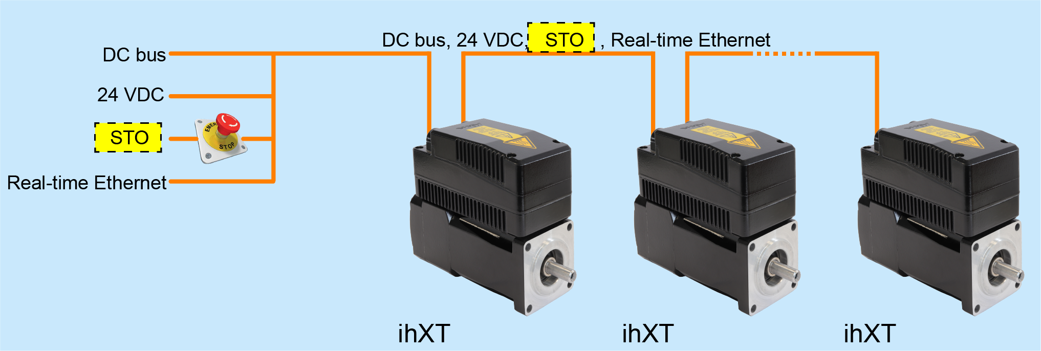
If the STO signal is looped through several drives, the STO state applies to all drives in this group. If a drive is in an error state due to a drive error (SBM = 0), it has no effect on the STO state of the other drives in this group.
STO with hybrid cable looped through in the drive train
Standards and characteristic values
|
Standards |
Topic |
Classification |
|---|---|---|
|
EN 61800-5-2 |
Safety function |
STO Safe torque off |
|
EN 60204-1 |
Stop category |
0 |
|
EN ISO 13849-1 |
Performance Level (PL) |
d |
|
Category |
3 |
|
|
IEC 61508 |
Safety integrated Level (SIL) |
2 |
|
EN 61131-2 |
Interface STO |
X08.1 and X08.2 (signal STO / STO_GND) |
|
Key values according to EN ISO 13849-1 |
Value |
Notice |
|---|---|---|
| PFH |
1,4 E-8 1/h |
1,4 % von SIL 2 |
| PFDavg (T = 20a) |
1,2 E-3 |
12 % von SIL 2 |
| MTTFd |
654 a |
high |
| DCavg |
74,2 % |
low |
|
Reaction times |
Value |
|---|---|
|
STO is triggered by hardware input |
< 5 ms |
|
Software reacts on error (error reaction) |
< 20 ms |
|
Diagnostic message is displayed |
< 200 ms |
|
Dynamization STO: The signal to control STO must be dynamic with a pulse duration |
≤ 1,5 ms |
Notes on operation
For your safety
|
|
|
|---|---|
|
|
Danger to life from touching electrical connections! In the status 'Safe torque off (STO)', the pulses for controlling of the output stage are blocked, the device remains connected to the mains (no automatic mains separation). Electrical terminals and connectors carry further voltages that may cause death or serious injury upon contact. Steps to prevent:
|


|
|
|
|
|
Danger to life due to unexpected movements! The drive will be torque-free in the status 'Safe torque off (STO)', in case of mains failure or in case of faulty drive controller. External application of force on the drive axis may result in life-threatening movements (e.g. hanging axes can fall down). Steps to prevent:
|

|
|
||
|---|---|---|
|
Behavior of the motor holding brake at STO
The STO state has no effect to the motor holding brake. The motor holding brake is supplied by connection X08.1 and X08.2 (signal 24V, 0V).
Hybrid cable
|
|
Cables like hybrid cable contains power, signal and communication wires as well as safety-relevant cables. Always install the safety related cables in accordance with EN ISO 13849-2 Table D.4 permanently (fixed) and protected against external damage, e.g. in the cable channel or armored tube. An energy chain can also be a suitable protection against external damage.
Consider possible causes of damage to cables and take appropriate preventive measures:
Further information on correct cable routing can be found in the standard EN 60204-1.
To prevent failure due to wear, replace cables when the maximum permissible number of bending cycles has been reached (relevant for cables that are subjected to cyclic bending, for example in a drag chain). The shield must be placed on PE on both sides. |

Assembly
Observe the installation instructions for heat dissipation so that the safety function is operated within the permissible temperature range.
Function test STO
Check STO safety function!
|
|
The achievable safety categories are only valid if the customer will performs the following checks:
|
Following states must be checked::
-
Switch contacts closed → STO inactive
Controller enable
Description
0
SBM = 1 - Regular operating state
Pulses enabled
No error messages
1
SBM = 1 - Regular operating state
QRF → PWM-control active
-
Switch contact STO or STO_GND interrupted → STO active
Controller enable
Description
0
SBM = 1 - Regular operating state
Safe pulse inhibitor
No error messages
1
SBM = 0
Safe pulse inhibitor
Error message 2320 'EF inactive'
-
Switch contact STO and STO_GND interrupted → STO active
Controller enable
Description
0
SBM = 1 - Regular operating state
Safe pulse inhibitor
No error messages
1
SBM = 0
Safe pulse inhibitor
Error message 2320 'EF inactive'
Further Information
See '[X08] Supply voltage 24 VDC and STO supply line'.
See '[X09] Transmission supply voltage 24 VDC and STO'.
